Issues with first Delta Robot.
The first delta robot created was very successful and was able to achieve basic movements in a simple pick and place application. In order for the robot to be more accurate and increase speed there were certain upgrades that needed to take place.
- Steal Arms - these arms were very stiff but also very heavy. This weight put a great deal of strain on the servo motors and decreased the robots overall accuracy as a result.
- Slow Ardunio Parsing - the commands sent to the Ardunio to drive the servos overflowed after a certain amount of use. Not ideal for fast and small incremental steps.
- Linear inverse kinematics motion - the trajectory of the first version was very linear, slow and only had an accuracy of 0.5cm.
- Inverse Kinematics Accuracy - lacked due to the overall weight of the delta arms. The further from the center, the less accurate the end effector would be.
- Large Gripper - while the original gripper was effective, it was also quite large
- Lack of Permanent Camera - the first delta robot versions camera was not accurately/stabliy mounted.
- Raspberry Pi - lacked computational requirements for certain applications.
The Goal
- Update the overall hardware of the delta robot. Make it lighter and stronger.
- improve trajectory algorithms and speed.
- improve accuracy using vision based calibration techniques.
- Solve Puzzles! Solving a jigsaw puzzle is a challenge in terms of picking and placing pieces and computer vision techniques.
The Updates
Arms
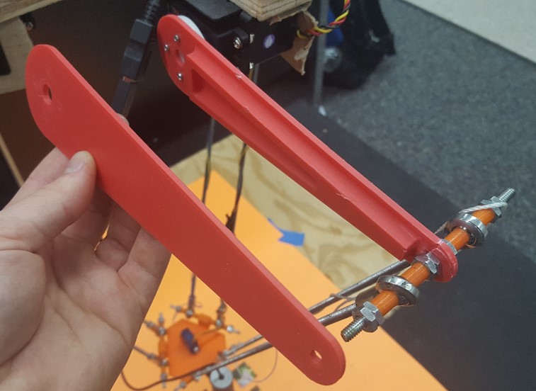
New arms were designed and 3D printed using ABS plastic to create an optimal balance of weight and stiffness. Initially a flat arm was printed with no support. This arm prooved to be very light but was not rigid enough. A triangular support was added to one side of the arm to add support but also try to minimizes weight. In the image below, the two iterations can be seen next to each other.
Gripper
The gripper was updated to be an electro-magnet. This is a more ideal gripper mechanism for picking up paper/cardboard pieces.
Initially self-made electro magnets were used. These proved to work but drew too much current and were too heavy.
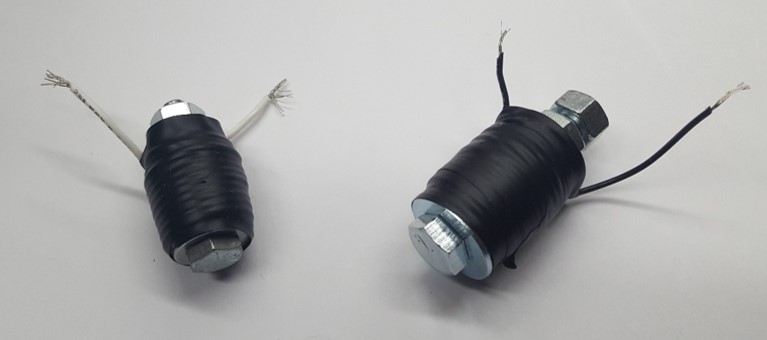
As a final solution, a Pixnor ZYE1-P2015 was purchased and attached to the “wrist” servo to provide rotation around the Z-axis. This electro-magnet is capable of holding 5.6lbs running off 12V and drawing 0.25A of current.
Camera
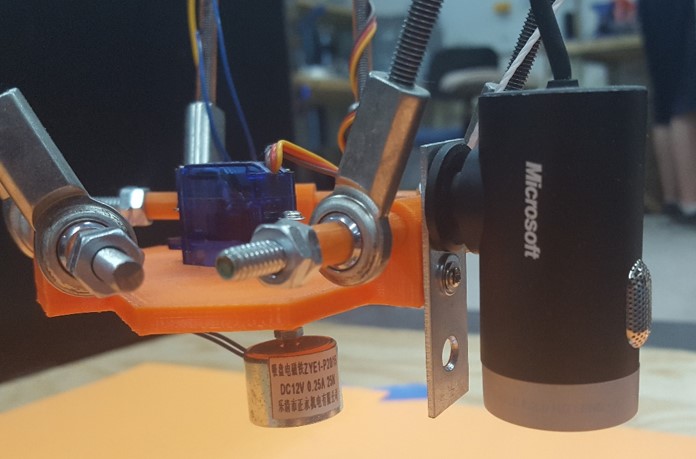
A Microsoft HD LifeCam was used as the primary webcam for this robot. It was ideal due to its slim profile, lightweight and HD quality images.
The image below consists of the securely mounted webcam and new electro-magnet.
Trajectory Planning
The delta robot was updated to achieve 5th Order Polynomial Trajectory Planning. This means the initial and final position, velocity and acceleration was constrained. The short video below is an example of the robots more direct and faster speeds.
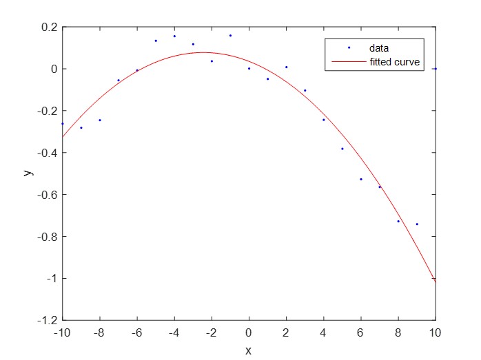
Error Tracking and Calibration
Due to the weight of the arms and flex in servo mounts, the delta needed to be properly calibrated to function properly. To accomplish this, the end effector of the robot needed to be tracked in 3D space. To accomplish this, a small white ball was attached to the bottom of the platform. Using a camera placed at a distance, the white ball was able to be tracked in one 2D plane at a time. The robot moved back along a singular axis and its position was graphed and fitted to a polynomial function. At any given point along the fitted curve, the difference from the accepted positon was used to offset the error. As a result, the delta robot was able to acheive much better accuracy and consitent positioning.
Puzzle Solving
To achieve puzzle solving, the delta robot (program) is given the final image to be solved. Given this, 3 main imaging mathcing technques were studied.
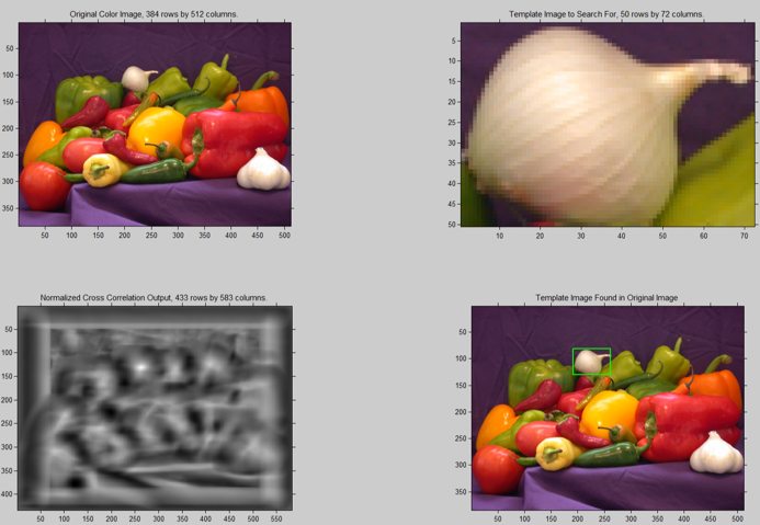
Cross Corelation
Determines the overall similarity between two images by directly comparing intensities. This technique is very accurate when comparing images on the same scale and orientation. Issues with cross correlation is that orientation of the images matters, can be a slow process, and not always accurate when using captured images from a webcam. In the image below, the image of the onion (upper right) is being cross correlated with the entire image (upper left). The brightest spot on the cross correltaion graph (botton left) can visually be observed by the highest intensity area.
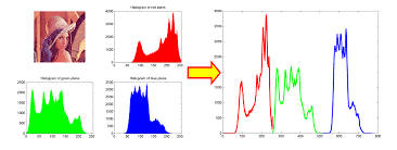
Color Histograms
SURF Features