System Level Design
I was on the Data Acquisition and Controls team (DAQCS). The DAQCS team was responsible for data and image acquisition, along with control of a reaction wheel to stabilize the platform. Furthermore, a Ground Recovery Signaling System (GRSS) is developed to easily locate the HABIP when it falls back to earth.
Below is a high level system diagram of the the DAQCS side. Here it can be seen that Raspberry Pi Zero’s are used for image/video and data acquisition. All of these nodes are powered via their own battery supply. A MSP430FR5994 is used as a host to manage all communication between the Raspberry Pi’s and the Communication subsystem. Another MSP430FR5994 is used to acquire local sensor data and control brushless motor that will be used as a reaction wheel capable of stabilizing the platform.
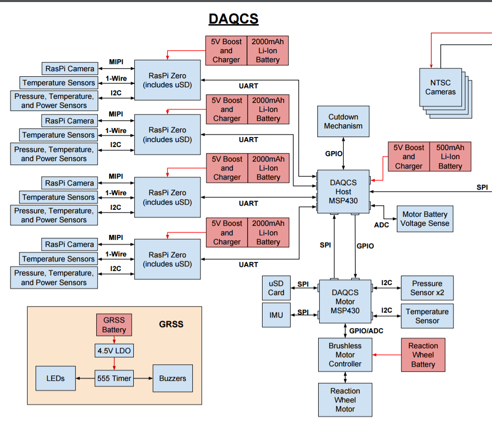
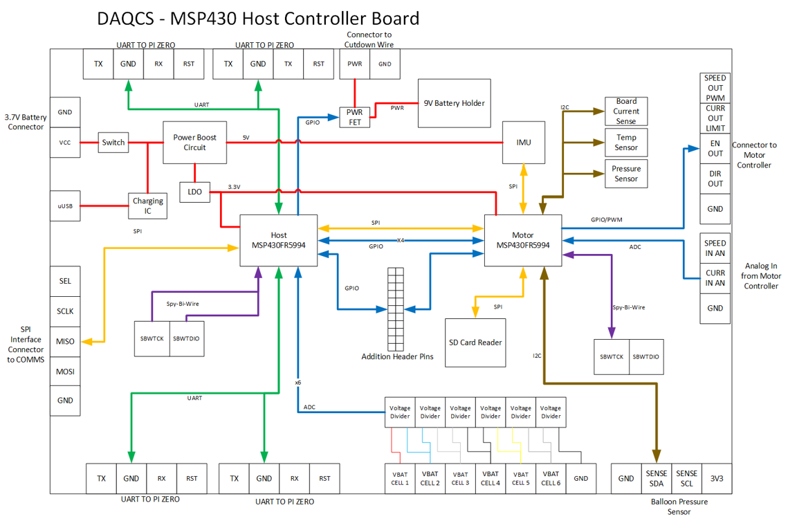
My main responsibility for this project was the design, build and development of the DAQCS Host Board. The main processing units powering the DAQCS Host Board are two MSP430FR5994 mixed-signal microcontrollers from Texas Instruments. The MSP430FR5994 uses embedded FRAM technology to allow for ultra-low power operation and robust operation in near space environments. This microcontroller is capable of 16MHz operation and a variety of peripherals including UART, SPI, I2C. Other features include a real time clock module and a 12-bit analog to digital converter. Overall, these capabilities make the MSP430FR5994 microcontroller an ideal choice for the high altitude balloon application. The required functionality is divided between two independent MSP430FR4994 microcontrollers. This is necessary to maintain performance and due to hardware peripheral limitations. The communication between all of the DAQCS sensor nodes and the COMMS host board is constrained to a single MSP430FR5994. This MSP430FR5994 will be referred to as the Host MSP430FR5994. This includes the communicating between the four DAQCS Sensor Nodes over UART interfaces, COMMS Host board over a SPI interface, and the second MSP430FR5994 over a SPI interface. All of these interfaces are implemented on separate hardware buses to allow for optimal performance. Furthermore, the Host MSP430FR5994 is responsible for controlling the safety cut-down mechanism and reading the reaction wheel battery voltage levels using the AC. The second MSP430FR5994, is responsible for reaction wheel motor control, acquiring local sensor data and storing data local to an SD card. This MSP430FR5994 will be referred to as the Motor MSP430FR5994. The Motor MSP430FR5994 will be able to receive commands and send data back to the Host MSP430FR5994 over a SPI interface. The Host MSP430FR5994 will be a master device and the Motor MSP430FR5994 will be a slave device. Overall, the DACQS Host board capable of executing all necessary functionality and also provides additional GPIO for future development. A high level diagram of the DAQCS Host controller board can be seen below.
Power Management
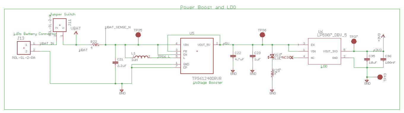
The DAQCS host board is to be powered via its own independent single cell 3.7V Li-Po battery pack. Therefore, proper voltage regulation is necessary to support all the devices on host board. The two main voltage levels that need to be obtained are 3.3V for the MSP430FR5994 and all I2C sensors, and 5V for the IMU. In order to accomplish this, a step-up DC-DC converter IC is used to step up the nominal 3.7V to 5V. A Texas Instruments, TPS61240 is chosen for this conversion. It supports a wide rage of input voltage levels and operates at efficiency rates at over 90%. This 5V supply is used to power the IMU. From the 5V supply, a LDO is used to step down the voltage to 3.3V. A Texas Instruments LP5907 is used for the conversion. It has a wide range of operating voltage levels and can provide up to 250mA of output current. This 3.3V supply provides power for both of the MSP430FR5994 microcontrollers. The 3.3V supply also provides power to the temperature sensor, pressure sensor, current sensor and the SD card. A detailed schematic can be seen below.
Host MSP430FR5994 System Design
The host MSP430FR5994 is primarily used as a communication terminal between all of the external subsystems. On the DAQCS side, communication between each of the Raspberry Pi Zero sensor nodes is accomplished using UART. The MSP430FR5994 is capable of four separate UART buses, therefore four sensor nodes will be used. This will allows data to be received from the sensor nodes and can interrupt the primary routine of the code to ensure the data is received. Data can also be sent to the sensor nodes to either update software parameters or to request data. Furthermore, a GPIO bus is connected to the sensor node which allows the Host MSP430FR5994 to hard reset the sensor node in case of failure.
The next major interface that the Host MSP430FR5994 handles is a SPI interface between the COMMS host Raspberry Pi Zero. In this configuration, the Host MSP430FR5994 is configured as a slave. This allows the COMMS Raspberry Pi to provide the master clock and send commands to request data from the Host MSP430FR5994. In this configuration, the Host MSP430FR5994 will receive and parse commands from the COMMS Host. If the command is directed at one of the Raspberry Pi sensor nodes or the Motor MSP430FR5994, the Host MSP430FR5994 will grab from the local register file in RAM and respond to the COMMS Host immediately. The Host MSP430FR5994 regularly polls each Raspberry Pi and the Motor MSP430FR5994 for all sensor values and stores the latest value in the local register file in RAM.
A SPI interface is also used to communicate between the Host and Motor MSP430FR5994. This allows commands to be sent from COMMS to be forwarded to the Motor MSP430FR5994. Such commands will include changing reaction wheel parameters and requesting current data. In this configuration, the Host MSP430FR5994 acts as the master SPI device and the Motor MSP430FR5994 acts as the slave device.
Apart from handling communications, the Host MSP430FR5994 is responsible for polling the status of the reaction wheel motor battery cells voltage levels. This feature is important since the Li-Po battery used in this initial application does not have built in under-voltage protection. Therefore, the voltage needs to be observed to ensure the voltage of each cell does not drop below a safe level. The 12-bit ADC will be able to acquire the analog voltage from each of the battery cells. The ADC will only operate up to a 2.5V reference. Each Li-Po cell has a maximum voltage of 4.2V. A voltage divider circuit is used to drop each cell down to a 2V max range. For protection, a 3V Zener diode is placed in parallel to each voltage divider to ensure a voltage over 3V is never seen at the output of each voltage divider.
Cutdown Mechanism
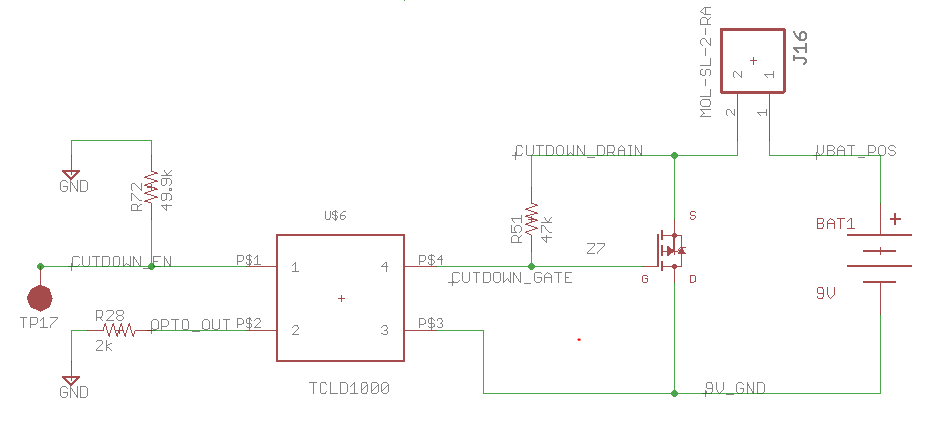
Finally, the Host MSP430FR5994 is responsible for controlling the cutdown mechanism. The cutdown mechanism is a small piece of nichrome wire at the end of a long copper wire cable. The end of the cable will be inside of the balloon envelope and resting along the side with the nichrome wire directly in contact with the balloon material. Shorting approximately one amp of current through this nichrome wire makes the nichrome heat up and pops the balloon. A separate 9V battery will be used as the power supply to heat up the nichrome wire. In order to safely create a short on the board, the circuit must be isolated from the main board circuitry. An optocoupler is used to isolate the control of a power MOSFET. A detailed schematic is seen below. When GPIO from the MSP430 is enabled high, this allows current to flow across the opposing side of the optocoupler. When this happens, the gate of the power MOSFET is pulled to GND (with respect the 9V battery) and therefore allows 1A of current to short across the source and drain of the MOSFET. This will consequently heat up the nichrome wire and pop the balloon. The Host controller will receive a command from the ground to initiate the cutdown sequence. In addition to this, when reaching a specific altitude calculated from the pressure sensors, the Host controller will initiate the cutdown sequence in the case that the ground loses communication with the platform.
Motor MSP430FR5994 System Design
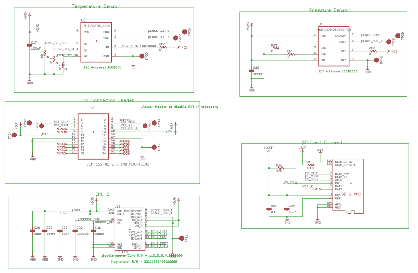
The motor MSP430FR5994 has five different sensors integrated on the board. Four of these sensors communicate over the same I2C bus. This include the temperature, pressure, current and backup IMU sensor. The current sensor allows to determine the current draw of the board throughout its operation. The backup IMU is a small IMU that is primarily used in cell phone based applications. The Host MSP430FR5994 also interfaces with an external I2C pressure sensor that will be located in the nozzle of the balloon. This sensor is on a separate I2C bus to minimize any failures or shorts that may occur.
The main IMU that will be used in the reaction wheel application is mounted on the board and interfaces with the MSP430FR5994 over a SPI interface. This IMU will be polled as fast as possible and used as an input to the reaction wheel controller algorithm. Detailed schematics of all sensors can be seen in Fig. 12 below.
GPIO/PWM Motor Controller
In order to control the motor controller, digital PWM signals and TTL signals are used. These signals are generated using the MSP430FR5994. The PWM is generated using built in timers on the MSP430FR5994 that are set to toggle a GPIO pin when the timer reaches a certain value. The timer count value can easily be modified on the fly to change the PWM duty cycle. Two separate PWM signals are generated. One is used to control the speed of the motor and the other is used to limit the max current consumed by the controller. Two GPIO pins are used to control if the controller is enabled and the direction to spin the motor.
ADC
The actual speed of the motor must be acquired as feedback for the reaction wheel controller. The Maxon motor controller outputs the current speed of the motor as an analog output that is scaled from 0-2.5V. Using the 12-bit ADC, the analog voltage can be acquired and converted to RPM.
All of the acquired data from sensors must be logged to an SD card such that the data can be analyzed after flight. A microSD card connector is mounted to the Host board and is interfaced with the Motor MSP430FR5994 over a SPI interface. This allows the MSP430FR5994 to create files and log data to the microSD card. The Motor MSP430FR5994 is a master device and the microSD card is the slave device. A detailed schematic of the microSD card interface can be seen below.
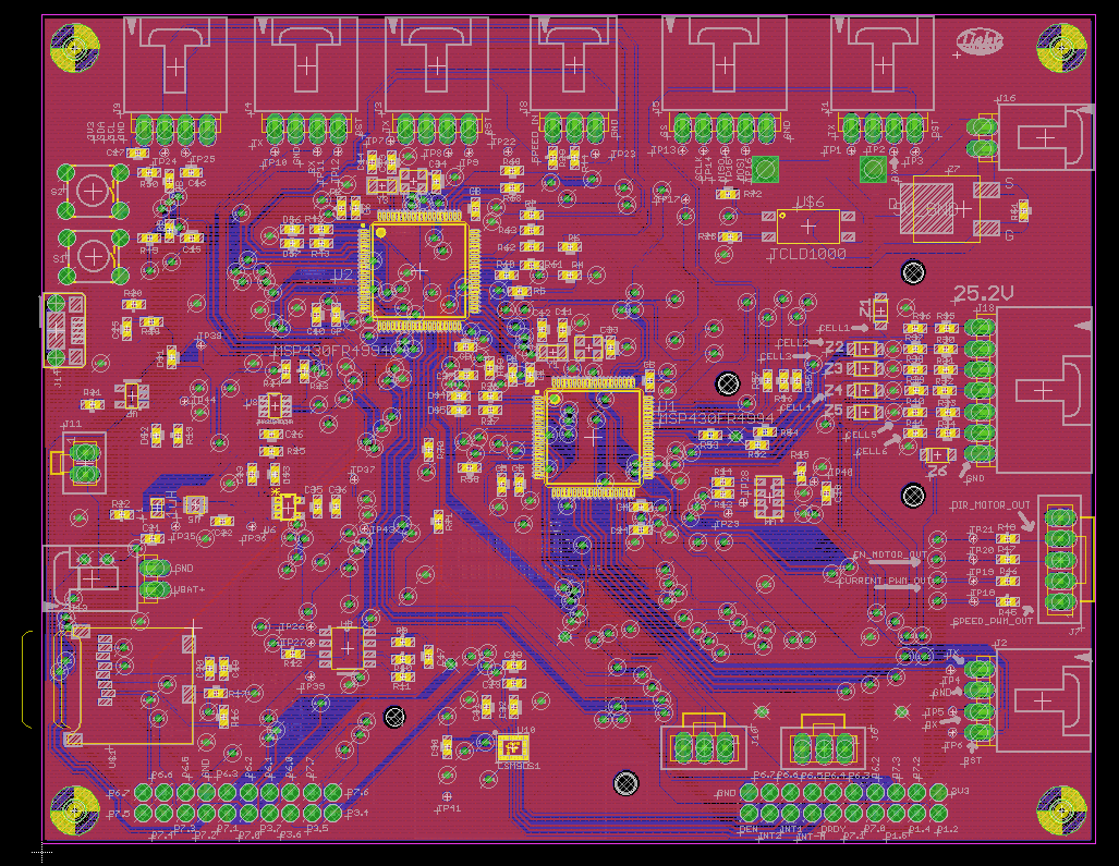
PCB Design
The 4-layer PCB layout was completed in Eagle PCB software. An image of the layout is captured below.
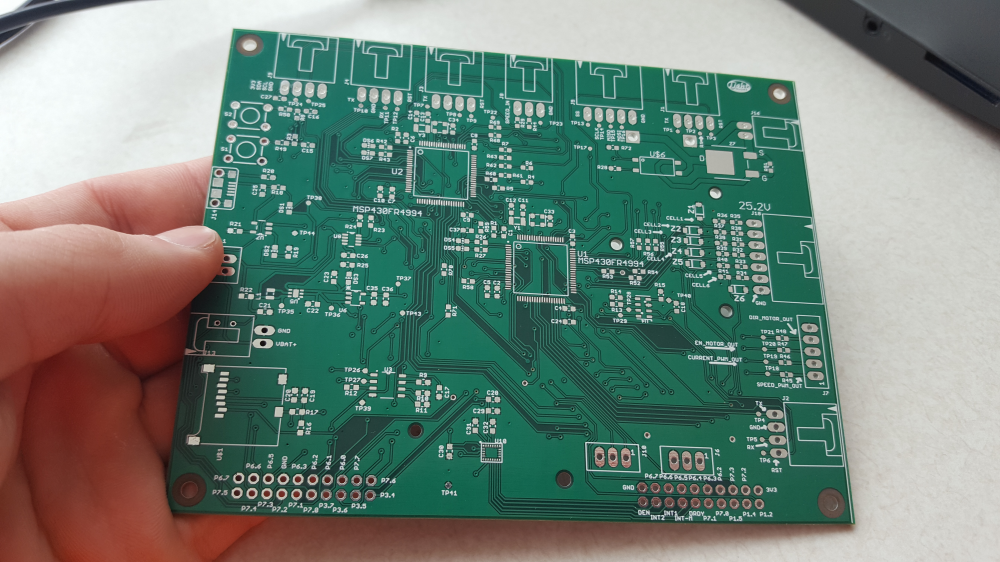
Bare Board
The bare board was manufacturer and can be seen below.
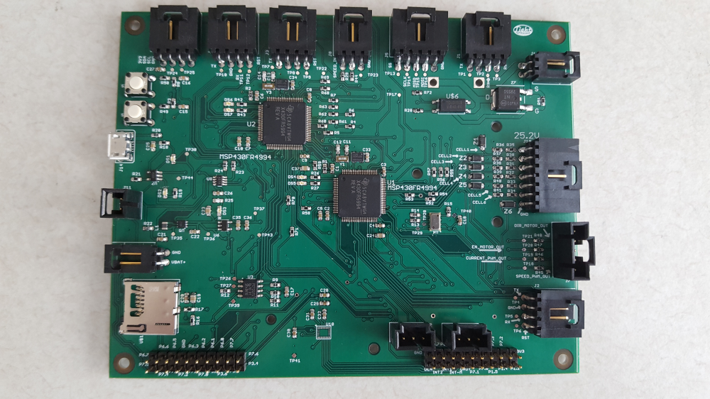
Assembled Board
Entire board was assembled by hand. Amazingly, the entire board is functional (and no magic smoke!)
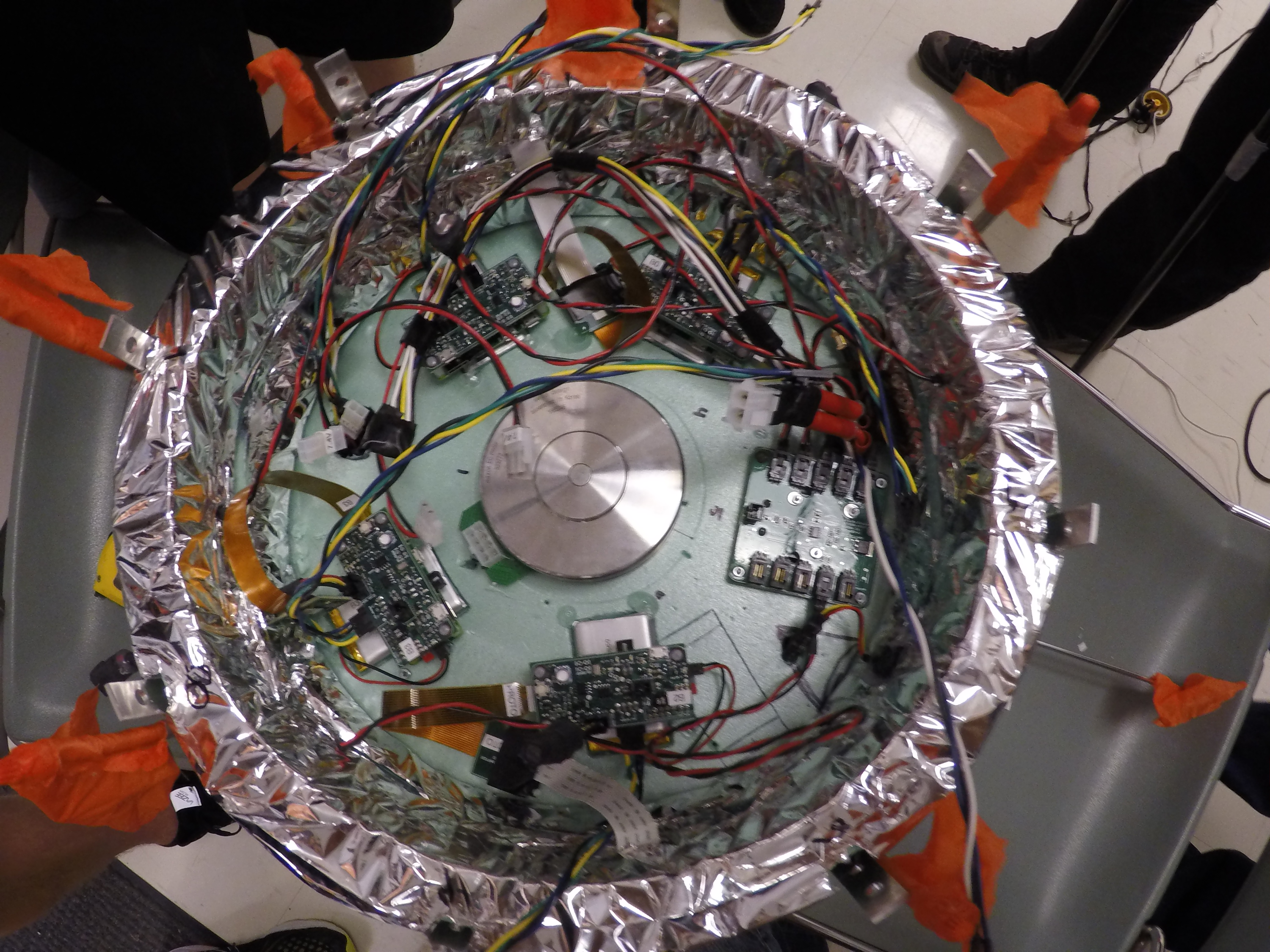
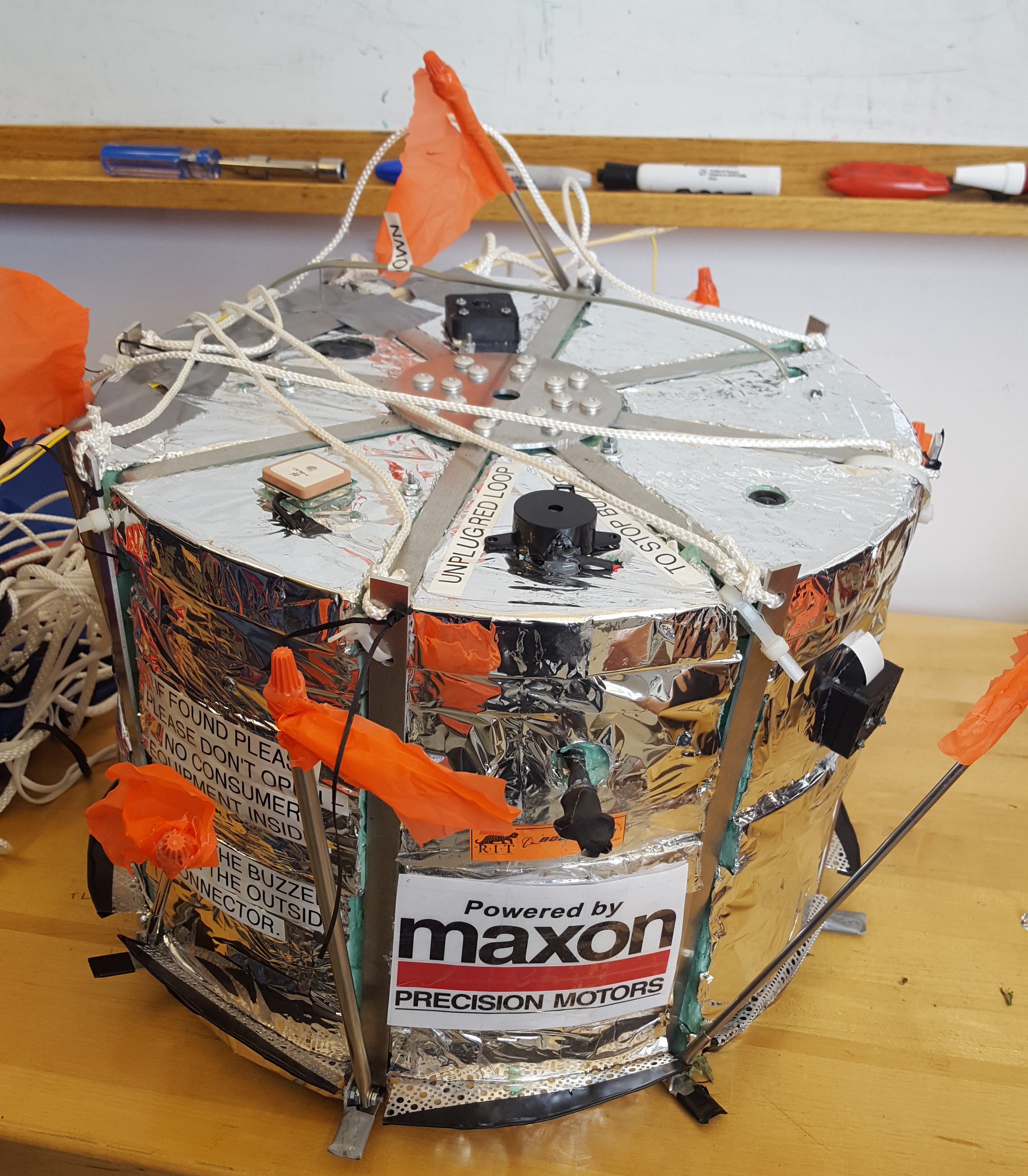
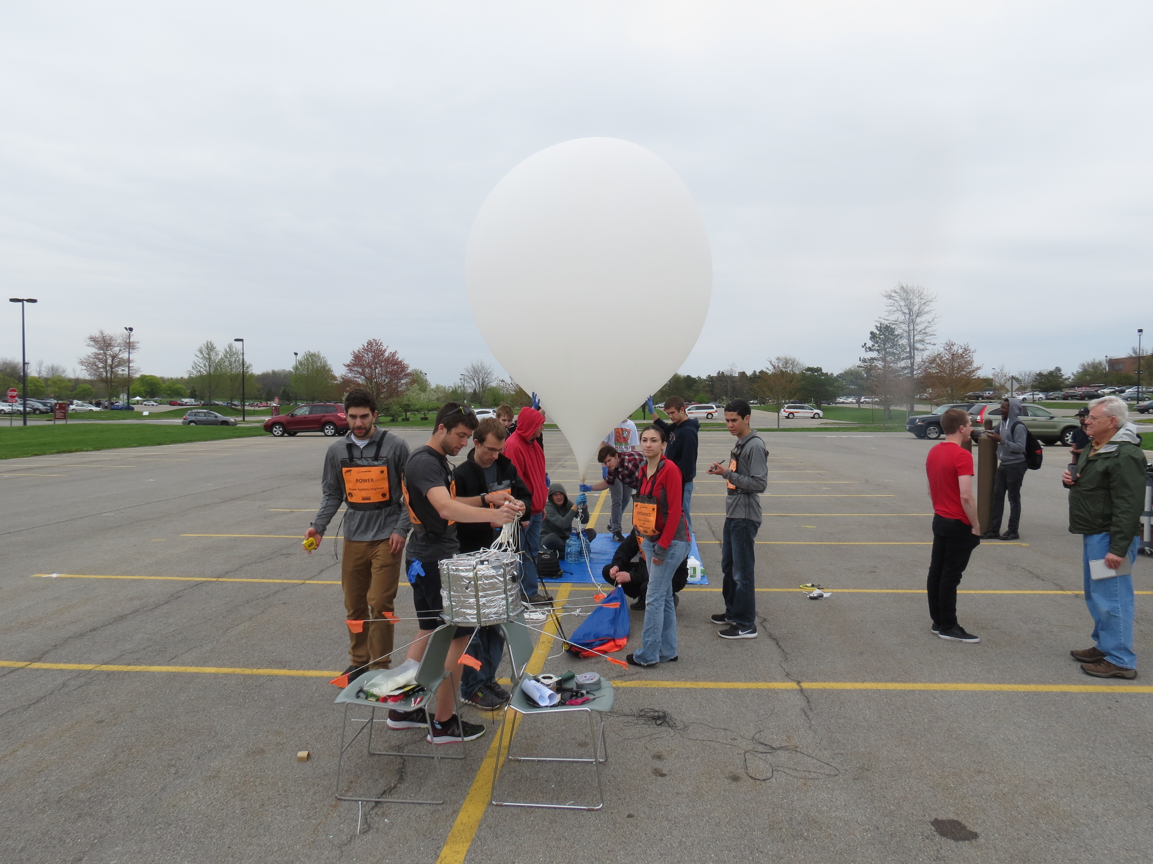
Final Design and Launch Day